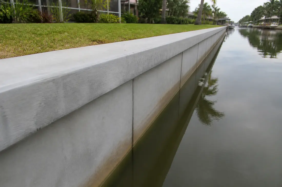
Somewhere in the process of getting a seawall repaired or replaced, most property owners on a Charlotte County canal end up asking a reasonable question: what does the building code actually require?
The answer is stranger than it ought to be.
The Florida Building Code contains exactly one section whose title is about seawalls. It is Section 1833, in Chapter 18, and its heading reads “High-Velocity Hurricane Zones—Seawalls and Bulkheads.” Look it up and the entire body of the section is one word: Reserved. There are no subsections, no requirements, and nothing to comply with.
Even if it were full of text, it would not apply here. The High-Velocity Hurricane Zone sections of Chapter 18 begin at Section 1817, and the code defines that zone precisely: it “consists of Broward and Miami-Dade counties.” Charlotte County is neither.
So there is no seawall chapter. That does not mean a seawall is unregulated — the state permitting question is a separate matter with its own rules, covered in our guide to when a seawall repair needs a permit. It means that structurally, a seawall is treated as what it physically is: a wall holding back soil, designed under the general provisions that apply to any such wall, with the engineer of record and the building official deciding how those provisions land on a particular marine structure.
Those general provisions are worth understanding, because they are short, they are numerical, and every number in them is a fact about your property that somebody has to go and establish. A proposal that never mentions any of them has not been designed. It has been priced.
Last reviewed: 7 October 2026 against the Florida Building Code, Building, 8th Edition (2023), Chapters 2, 16 and 18.
Four ways a retaining wall fails, named in one sentence
Section 1807.2.1 is the general requirement, and it is unusually direct about what can go wrong. Retaining walls “shall be designed to ensure stability against overturning, sliding, excessive foundation pressure and water uplift.”
Four failure modes, and a seawall can suffer all of them. Overturning is the wall rotating forward at the top. Sliding is the whole wall translating toward the water. Excessive foundation pressure is the base punching down into soil that cannot carry it. Water uplift is pressure from below, lifting the structure.
The same section adds a detail that only matters once you know what it refers to. Where a keyway — a lip extending below the wall base — is used to engage passive pressure and improve resistance to sliding, “lateral soil pressures on both sides of the keyway shall be considered in the sliding analysis.” A keyway is not free resistance. The soil pushes on both of its faces, and a design that counts only the helpful side has overstated what the keyway does.
Section 1807.2.3 then sets the margin, and it is worth reading as adopted. Retaining walls “shall be designed to resist the lateral action of soil to produce sliding and overturning with a minimum safety factor of 1.5 in each case. The load combinations of Section 1605 shall not apply to this requirement. Instead, design shall be based on 1.0 times all applicable nominal loads, and investigation with one or more of the variable loads set to zero.”
Not an overall 1.5 — 1.5 for each of the two, separately. And the section says how the sliding figure is arrived at: “The safety factor against lateral sliding shall be taken as the available soil resistance at the base of the retaining wall foundation divided by the net lateral force applied to the retaining wall.”
Available resistance over applied force — which is why what the soil can offer at the base of the wall, covered next, is half of the sliding question rather than a footnote to it.
That is the whole structural standard in three short paragraphs. Everything else is working out what the loads are.
The load behind the wall, and the number that doubles it
Section 1807.2.2 is one line: retaining walls “shall be designed for the lateral soil loads set forth in Section 1610.”
Section 1610 is headed “Soil Loads and Hydrostatic Pressure,” and Table 1610.1 is the table that matters. It lists backfill materials by their Unified Soil Classification and gives two columns of design lateral soil load, in pounds per square foot per foot of depth.
Take the clean sands — SW and SP, well-graded and poorly graded clean sands and gravelly sand mixes. The table gives 30 psf per foot of depth in one column and 60 psf per foot in the other.
Which column applies is decided by one question, and it is the most consequential sentence in the section: “Foundation walls and other walls in which horizontal movement is restricted at the top shall be designed for at-rest pressure. Retaining walls free to move and rotate at the top shall be permitted to be designed for active pressure.”
Active pressure is the lower number. It is what the soil pushes with once the wall has moved slightly away from it and the soil has relaxed into a shearing state. A wall that is free to rotate at the top gets to use it. A wall whose top is held — by a cap tied into something, by an anchor, by a slab — never lets the soil relax, so it carries the at-rest pressure instead.
For clean sand that is the difference between 30 and 60. The restrained wall is designed for twice the lateral load of the free one, for identical soil at identical depth.
The table is also an education in backfill. Silty sands (SM) are 45 active and 60 at-rest. Clayey sands (SC) are 60 and 100. Inorganic clays of low to medium plasticity (CL) are 60 and 100. And four classifications — organic silts (OL), elastic silts (MH), high-plasticity clays (CH) and organic clays (OH) — carry no numbers at all. The footnote against them reads “Unsuitable as backfill material.”
One more footnote is worth reading before trusting any of it: the values “are given for moist conditions at optimum densities,” and “actual field conditions shall govern.” The table is a floor for design, not a description of your canal bank. The section opens by saying these loads are the minimum “unless determined otherwise by a geotechnical investigation in accordance with Section 1803,” and soil classification is to comply with ASTM D2487.
Drainage is not a detail. It is a load case.
One provision in Section 1610.1 changes what the wall is being designed against, and it turns on whether the backfill can drain.
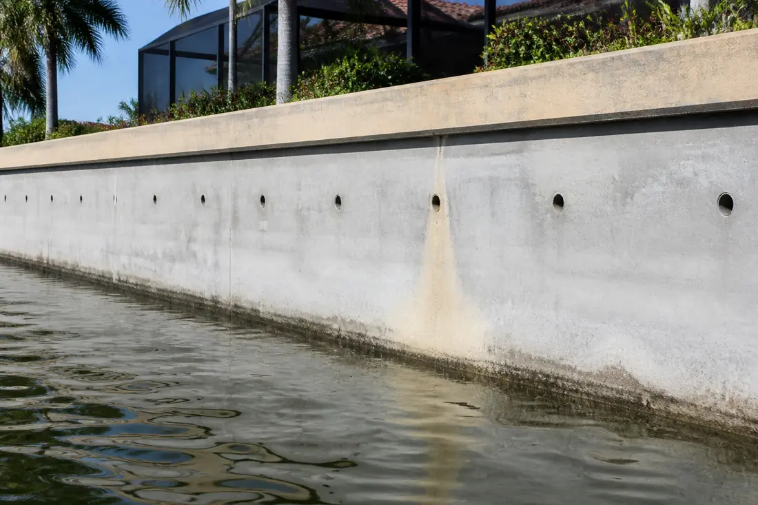
Section 1610.1 states that foundation walls “shall be designed to support the weight of the full hydrostatic pressure of undrained backfill unless a drainage system is installed in accordance with Sections 1805.4.2 and 1805.4.3.”
Read that as the engineering trade it is. A drainage system is not an optional improvement that extends the life of the wall. It is the thing that allows the wall to be designed for soil pressure alone. Without it, the design has to assume the backfill is saturated and carry the full pressure of standing water behind the structure, which is a substantially larger load than moist sand.
The code sets no single number for that case, because it depends on how far up the backfill the water stands. What it does is swap the question: instead of the 30 psf per foot that Table 1610.1 allows for drained clean sand under active conditions, the undrained wall is designed against the weight of the water itself over the saturated depth. The wall that was never drained, or whose weep holes silted up a decade ago, is carrying a load case its design may never have contemplated.
That is why a fan of pale soil staining the wall below a weep hole is worth more attention than it looks. It means the drainage path is live and is carrying fines out of the backfill with the water, which relieves pressure and hollows the ground behind the wall at the same time. A weep hole that has never stained anything may simply be blocked.
Section 1610.2 covers the other direction: elements below grade are designed to resist uplift, and “the upward pressure of water shall be taken as the full hydrostatic pressure applied over the entire area.” No reduction, no averaging — the whole footprint.
There is one exception in 1610.1 worth knowing, because it is narrow and gets misquoted. Foundation walls “extending not more than 8 feet below grade and laterally supported at the top by flexible diaphragms” are permitted to be designed for active pressure. Both conditions have to hold, and the depth limit is explicit. It is not a general permission to use the lower number.
What the soil can carry back
Loads are only half of it. Table 1806.2 gives the presumptive values for what the ground can resist, and the numbers are modest.
For Class 4 materials — sand, silty sand, clayey sand, silty gravel and clayey gravel (SW, SP, SM, SC, GM and GC) — the table allows 2,000 psf vertical foundation pressure, 150 psf per foot below grade of lateral bearing pressure, and a coefficient of friction of 0.25 for sliding resistance.
Class 3, sandy gravel and gravel, does better: 3,000 psf, 200 psf per foot, and 0.35. Class 5, the clays and silts, drops to 1,500 psf vertical and 100 psf per foot, and instead of a friction coefficient it gets a cohesion value of 130 psf.
The friction coefficient is multiplied by the dead load, which is the detail that makes a light structure a harder problem than a heavy one. Resistance to sliding is bought partly with weight.
Section 1806.2 also draws a line that matters on filled waterfront lots: mud, organic silt, organic clays, peat and unprepared fill “cannot be assumed to have a presumptive load-bearing capacity” unless data exist to support it. If what is under the wall is fill of unknown origin, the table does not answer the question and a geotechnical investigation does.
Section 1806.1 adds that these presumptive values are used with the allowable stress design load combinations, and may be increased by one-third where the alternative combinations including wind loads apply.
How the code sizes an embedded post or pole
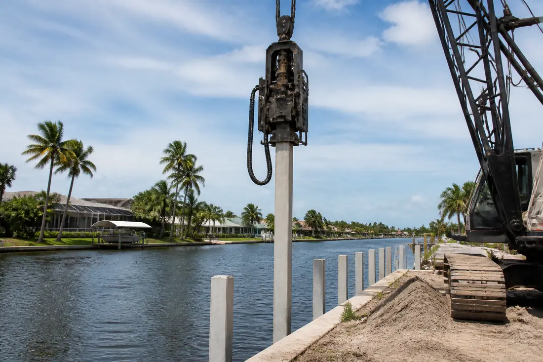
Section 1807.3 is the part of this chapter that produces an actual depth, and it is the closest the code comes to telling anyone how far down to go. It applies to embedded posts and poles — round or square posts and their footings — which makes it directly relevant to dock pilings and to king piles, and not to a continuous sheet pile wall, which is designed by other means.
The code splits it in two. Section 1807.3.2.1 covers the unconstrained case — no lateral restraint at the ground surface, and none above it — and gives the required depth as Equation 18-1. Section 1807.3.2.2 covers the constrained case, where a rigid floor or pavement holds the post at grade, with Equations 18-2 and 18-3 working from the moment in the post at grade.
The equations themselves are published in the code as figures rather than as running text, and they are not reproduced here. Anyone sizing a member works from the code, not from an article’s transcription of it. What is worth knowing is what goes into them, because those are the things a property owner can actually ask about:
- P, the applied lateral force, in pounds
- h, the distance from the ground surface to the point where that force acts
- b, the diameter of the round post or footing, or the diagonal dimension of a square one, in feet
- S₁ or S₃, the allowable lateral soil-bearing pressure from Section 1806.2 — the 150 psf per foot of depth figure above, for Class 4 material
The difference between S₁ and S₃ is the part that rewards attention. In the unconstrained case the allowable pressure is taken, in the code’s words, “based on a depth of one-third the depth of embedment.” In the constrained case it is taken at a depth equal to the full depth of embedment. The same soil gives a different allowable pressure depending on whether the top of the post is held — the same principle as the at-rest versus active question above, arriving from a different direction.
Two further things are worth a non-engineer’s attention.
The first is that the depth used “for purpose of computing lateral pressure” is capped: the definition of d reads “not over 12 feet.” The method does not keep rewarding you indefinitely for driving deeper, which is consistent with what the Corps manual says about the failure modes that more penetration cannot fix — covered in our guide to what is actually holding your seawall up.
The second is that every term is a measurement of your site. The soil class, the applied load, the height at which it acts, the diameter of the member. Change the soil class from Class 4 to Class 5 and the allowable lateral bearing pressure drops from 150 psf per foot to 100, and the required depth moves with it.
Section 1807.3.2 also leaves an explicit door open: the depth may be determined by these criteria “or by other methods approved by the building official.” Engineered design is the normal route for anything load-bearing on the water, and the equations are a floor rather than a ceiling.
Section 1807.3.1 carries two limitations that catch people. Frictional resistance for structural walls and slabs on silts and clays is limited to one-half of the normal force imposed by the weight of the footing or slab. And wood poles are to be treated in accordance with AWPA U1 — Commodity Specification A for sawn timber posts and Commodity Specification B for round timber posts, both Use Category 4B. The code names that use category specifically, which makes it something a supplier has to match on the tag rather than a general instruction to buy treated wood.
The backfill has its own rules
Section 1807.3.3 covers the annular space around a column that is not embedded in a poured footing, and permits three methods.
Concrete backfill, with a specified compressive strength of not less than 2,000 psi, in a hole not less than 4 inches larger than the diameter of the column at its bottom — or 4 inches larger than the diagonal dimension of a square or rectangular column.
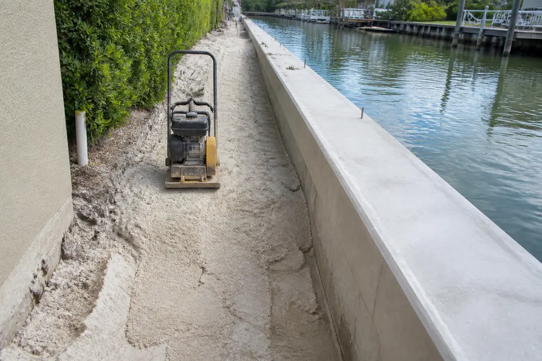
Clean sand, “thoroughly compacted by tamping in layers not more than 8 inches in depth.”
Or controlled low-strength material, the flowable fill that self-levels and needs no compaction at all.
The 8-inch lift is the one that gets skipped on a hurried job, and it is also the one nobody can inspect afterwards. Backfill dumped in a single two-foot lift and walked on is not compacted sand in the sense the code means, and the settlement shows up later as a hollow in the lawn rather than as anything visible on the wall.
What a professional establishes, in order
Working from the code backwards, the sequence of things that have to be known before a number can be put on a wall runs roughly like this.
First, the retained height and the water level — the geometry, because every pressure in Section 1610 is per foot of depth and nothing can be computed without it.
Second, the soil, classified rather than described. The difference between SP and SC in Table 1610.1 is 30 versus 60 psf per foot active, and the difference between Class 4 and Class 5 in Table 1806.2 changes what the ground can push back with. “Sand” is not a classification.
Third, whether the top of the wall is restrained. This is the at-rest versus active question, and it is answered by looking at what the cap is connected to, not by assumption.
Fourth, the drainage. Whether a system exists, whether it functions, and therefore whether the design can use soil pressure alone or has to carry full hydrostatic pressure.
Fifth, the surcharge. What sits on the ground behind the wall — a pool deck, a driveway, a seawall-side slab — adds load that the bare tables do not include.
Only then does anyone have the inputs to say whether the existing wall is adequate, and what a replacement would have to be.
Common mistakes
Assuming the absence of a seawall section means there are no requirements. Section 1833 being reserved does not remove a wall from Chapter 18. It means the general retaining wall and foundation provisions, plus engineered design, are the route.
Quoting a High-Velocity Hurricane Zone section as though it applied. Chapter 18’s HVHZ sections start at 1817 and reach Broward and Miami-Dade only. The same trap exists in several chapters of this code, and reading the section heading before relying on it is the whole defense.
Treating drainage as maintenance rather than as design. If the wall was designed on the assumption that the backfill drains, then the drainage is structural, and a blocked weep hole is a change to the load case.
Using active pressure on a wall that is restrained at the top. It halves the design load on paper and changes nothing about the soil.
Backfilling with whatever came out of the hole. Four Unified Soil Classifications are listed in Table 1610.1 as unsuitable as backfill material, and organic material excavated from a canal bank can easily be one of them.
What drives the cost
There is no meaningful price for seawall work without knowing the retained height, the soil classification, whether the top of the wall is restrained, whether drainage exists and functions, and what surcharge sits behind it. Those five answers determine what is being built, not merely what it costs.
The variable owners consistently underestimate is the retained side. A wall face can be replaced for a figure that is roughly predictable from its length. Voids behind the wall, unsuitable backfill that has to come out and be replaced, and a drainage system that has to be built rather than cleaned are all discovered after the work starts, and each of them is a larger number than the panel it sits behind.
Before you accept a proposal
Ask which lateral soil load the design used, and whether it is the active or the at-rest value. The answer tells you immediately whether anyone considered how the top of the wall is restrained.
Ask what the soil classification is and how it was established. If the answer is a Unified Soil Classification letter pair, the ground has been looked at. If it is “sand,” it has not.
Ask what the drainage provision is, and whether the design assumes drained or undrained backfill. These are two different walls at the same height.
Ask what the embedment depth is and what it was derived from. For an embedded post or pole there is a formula; for a sheet pile wall there is an engineered design. Either way there is a basis, and it should be possible to state it.
And ask for the engineer of record. On a structure that retains soil against water, that is the person whose numbers these are.
If you are trying to work out whether an existing wall is in trouble, an inspection that establishes the retained height, the soil and the drainage is the useful first step — before anyone quotes a panel. Our pages on seawall inspection and seawall drainage and weep holes set out what each involves.
This guide explains the code provisions in plain language and is not legal advice or an engineering design. The adopted code, a registered design professional’s analysis of a specific wall, and the building official’s determination for a specific property control what is actually required.
Sources
- Florida Building Code, Building, 8th Edition (2023), Chapter 18 — Soils and Foundations. Load combinations and the one-third increase at Section 1806.1; presumptive load-bearing values, the exclusion of mud, organic silt, organic clays, peat and unprepared fill, and Table 1806.2 with its vertical, lateral bearing, friction and cohesion columns at 1806.2; retaining wall stability against overturning, sliding, excessive foundation pressure and water uplift, and the keyway provision, at 1807.2.1; the pointer to Section 1610 at 1807.2.2; the 1.5 safety factor in each case, the disapplication of the Section 1605 load combinations, the “1.0 times all applicable nominal loads” basis and the definition of the safety factor against lateral sliding at 1807.2.3 — re-read verbatim on 7 Oct 2026, and the section as Florida adopts it carries no earthquake or seismic wording; the limitations and the AWPA U1 Use Category 4B requirement at 1807.3.1; the design criteria and the building official’s alternative at 1807.3.2; the nonconstrained case, Equation 18-1, the definitions of P, h, b and S₁ and the “not over 12 feet” limit at 1807.3.2.1; the constrained case and Equations 18-2 and 18-3 at 1807.3.2.2 — the equations are published as figures rather than as text and are deliberately not transcribed in this article; vertical load at 1807.3.2.3; the three backfill methods, the 2,000 psi concrete, the 4-inch oversize and the 8-inch sand lifts at 1807.3.3; the High-Velocity Hurricane Zone sections beginning at 1817; and Section 1833, “High-Velocity Hurricane Zones—Seawalls and Bulkheads,” whose body reads “Reserved.”
- Florida Building Code, Building, 8th Edition (2023), Chapter 16 — Structural Design. Section 1610, “Soil Loads and Hydrostatic Pressure”: lateral pressures, the at-rest versus active rule, the full hydrostatic pressure of undrained backfill unless drained per Sections 1805.4.2 and 1805.4.3, and the 8-foot flexible-diaphragm exception at 1610.1; Table 1610.1, lateral soil load by Unified Soil Classification with its active and at-rest columns, the “unsuitable as backfill material” note and the ASTM D2487 reference; and uplift at full hydrostatic pressure over the entire area at 1610.2.
- Florida Building Code, Building, 8th Edition (2023), Chapter 2 — Definitions. The High Velocity Hurricane Zone, which “consists of Broward and Miami-Dade counties.”