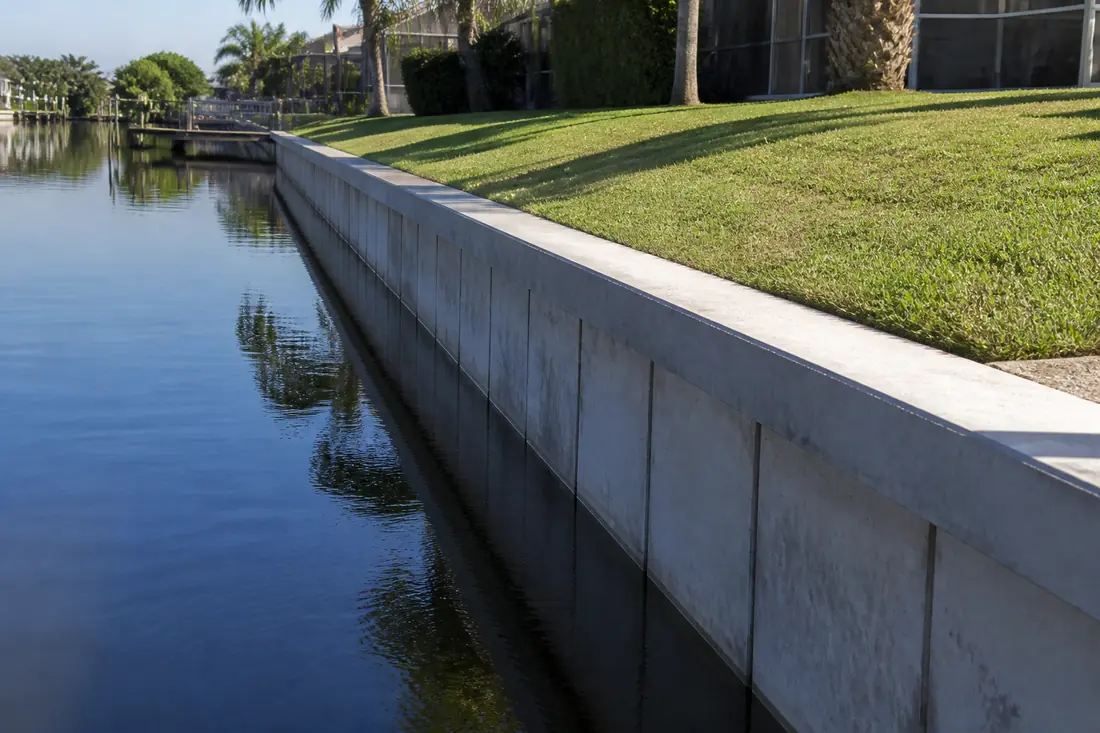
Your seawall looks like a wall. A cap along the top, a face going down into the water, and behind it the lawn. It reads as one object, and the natural assumption is that whatever is wrong with it is wrong with the part you can see.
The face is the least of it. Structurally, a seawall is one of two quite different things, and which one you have decides what a repair can and cannot achieve — and whether a problem developing today is fixable at all.
The clearest published description of how these structures work is a U.S. Army Corps of Engineers design manual, EM 1110-2-2504, Design of Sheet Pile Walls. It is a civil works manual for Corps projects, not a residential standard and not the code your seawall was permitted under. It is useful here because it names the mechanisms plainly, and the mechanisms do not change with the size of the job.
Last reviewed: 17 September 2026 against EM 1110-2-2504 (31 March 1994) and the Florida Building Code, Building, 8th Edition (2023).
Two structures, one appearance
The manual’s definitions section separates them.
A retaining wall is “a sheet pile wall (cantilever or anchored) which sustains a difference in soil surface elevation from one side to the other,” where the change in elevations may be produced by excavation, dredging, backfilling, or a combination.
An anchored wall is “a sheet pile wall which derives its support from a combination of interaction with the surrounding soil and one (or more) mechanical devices which inhibit motion at an isolated point(s).”
A cantilever wall has no such device. It stands because of what is buried.
The manual also gives the vocabulary that makes an inspection report readable. The dredge side is the side with the lower soil surface elevation — the canal side. The retained side is the higher side — your yard. Backfill is “a generic term applied to the material on the retained side of the wall.” Penetration is “the depth to which the sheet piling is driven below the dredge line.” And anchorage is “a mechanical assemblage consisting of wales, tie rods, and anchors which supplement soil support for an anchored wall.”
Those five words appear in nearly every seawall quote, and most homeowners meet them for the first time in a document they are being asked to sign.
The failure mode that cannot be fixed by going deeper
Chapter 5 of the manual sets out the modes of failure, and the first one is the one worth knowing about.
Deep-seated failure is “a potential rotational failure of an entire soil mass containing an anchored or cantilever wall,” and the manual says it is “independent of the structural characteristics of the wall and/or anchor.” Then the sentence that should change how anyone reads a repair proposal:
“This type of failure cannot be remedied by increasing the depth of penetration nor by repositioning the anchor. The only recourse when this type of failure is anticipated is to change the geometry of retained material or improve the soil strengths.”
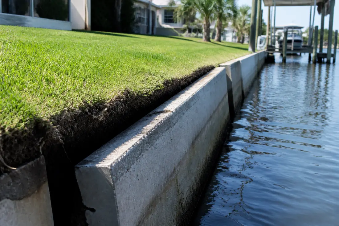
So there is a category of movement where a longer sheet, a new tieback and a heavier cap all address the wrong thing. The manual directs that the adequacy against this mode be assessed by a geotechnical engineer through conventional slope stability analyses.
The second mode is the intuitive one. Rotational failure due to inadequate pile penetration: lateral soil and water pressures “tend to cause rigid body rotation of a cantilever or anchored wall.” This one is prevented by adequate penetration in a cantilever wall, or by “a proper combination of penetration and anchor position” in an anchored wall.
The third is structural — failure “initiated by overstressing of the sheet piling and/or anchor components.”
Three modes, three different remedies. A wall leaning towards the canal is displaying a symptom that fits all three, which is exactly why the diagnosis matters more than the lean.
What a design actually needs to know
Section 5-2 lists the preliminary information that must be established before design can commence, and the list is a useful measure of how thorough a proposal is.
The elevation at the top of the sheet piling. The ground surface profile “extending to a minimum distance of 10 times the exposed height of the wall on either side.” The soil profile on each side including the location and slope of subsurface layer boundaries, strength parameters and unit weight for each layer, “to a depth below the dredge line not less than five times the exposed height of the wall on each side.” Water elevation on each side and seepage characteristics. Magnitudes and locations of surface surcharge loads. And magnitudes and locations of external loads applied directly to the wall.
Read the two multipliers. Ten times the exposed height, horizontally. Five times the exposed height, downward. On a wall standing six feet above the dredge line that is 60 feet of ground profile each way and 30 feet of soil information below the bottom of the visible structure.
Surcharge loads are worth noticing too. A pool deck, a driveway, a stack of pavers or a truck parked near the edge is a surface surcharge, and it is an input to the design rather than an incidental detail.
Corrosion concentrates in one narrow band
Section 9-2 describes the corrosion process as electrochemical, “highly dependent on the environment in which it is placed,” and gives figures for exposed steel sheet piling: uncapped exposed sheet pile “corrodes at varying rates averaging from 2 to 10 mils per year depending on the surrounding atmospheric conditions,” with rates usually decreasing after the first few years of exposure.
Then the geography of it. Sheet pile driven in natural undisturbed soil has “a negligible corrosion rate due to the deficiency of oxygen at levels just below the groundline,” while increased rates “for piles in organic or fresh fills should be anticipated due to oxygen replenishment.”
And in water: “fresh water is the least corrosive and salt water the most, with contaminants and pollutants playing a major role in magnifying its corrosiveness. The critical zone for sheet piles exposed to water is the splash zone, the area between the still water elevation and the upper limit of wave action. This area corrodes at a much greater rate than if it remained completely submerged.”
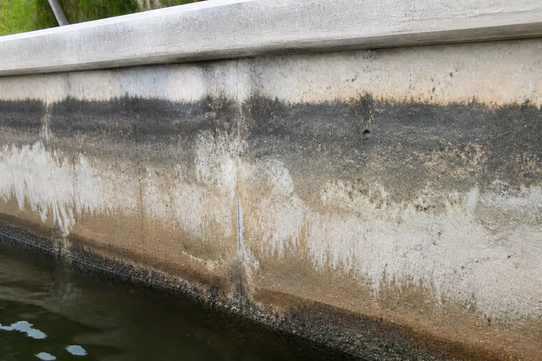
The splash zone is a band you can reach from a kayak, and it is the part of the structure most likely to be losing section. It is also the part that gets looked at least, because it is below the cap and above the water and there is nothing obvious to see until there is.
The manual notes two responses used on Corps work: providing electrical continuity in capped walls by running a continuous No. 6 rebar atop the piling, welded at each section and terminating at monolith joints with a flexible jumper, so that the system can later be externally charged to suppress corrosion; and specifying a larger sheet pile section “to provide for the anticipated loss of section resulting from corrosion.” Both are design decisions made before anything is driven.
Anchors are as much about construction as about design
Section 8-10 is short and its subject is not calculation. “Improperly planned construction methods may produce loads which exceed those used for design. Anchor forces, soil pressures, and water loads are affected by the method of construction and construction practices.”
The specifics: the sequence of tightening tie rods should be specified, to prevent overstresses in isolated sections of the wale or the wall. Anchors and tie rods should be placed and tightened “in a uniform manner so that no overstresses may occur.” Backfilling above the anchor elevation should be carefully controlled to prevent bending of the tie rods, and the backfill material controlled with the thickness of compacted layers limited “to ensure proper compaction and drainage of the backfill material.”
Section 9-4 adds a related warning: tie rods placed above loose granular or soft cohesive soils “can be subjected to loads greater than that computed by conventional methods,” because as underlying soils compress the weight of the overlying soils induces additional load as the rod deflects. Where excavation is necessary to place an anchor, the backfilled material “should be a select soil, compacted to at least 90 percent of standard proctor maximum dry density.”
The theme across all of it is that a correctly designed anchored wall can still be built into a problem, and the problem is created by backfill practice rather than by the anchor.
Section 8-9 gives the driving tolerances on Corps work: a vertical tolerance of plus or minus 1 1/2 inches from design elevation, and piling driven no more than 1/8 inch per foot out of plumb, either in the plane of the wall or perpendicular to it.
What an inspector looks for, in order
The lean, measured rather than eyeballed. A plumb reading at several points along the wall tells you whether there is rotation, and whether it is uniform or localized.
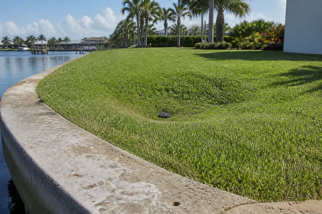
The ground behind it. Section 9-8 of the manual notes that scour problems should be monitored and corrected “if the stability of a vertical sheet pile wall is affected.” Depressions in the lawn, low sprinkler heads and settled slabs are the retained side telling you material has moved.
The splash zone. Where loss of section happens fastest, per Section 9-2.
The cap. Section 9-8 again: “concrete capping should be inspected for cracking and sealed as needed to prevent intrusion of foreign materials.”
Whether the wall is anchored at all, and if so, where the anchors are. That is the question that determines which failure mode is even available.
Repair or replace
Section 9-8 states the Corps position in one sentence: structures “that have sustained major damage from storms or have deteriorated to a point at which normal maintenance is impractical may require total rehabilitation. At this time consideration should be given to alternative types of structures.”
Translated to a residential canal, the decision usually turns on three facts.
Which failure mode. Deep-seated movement is not repairable by working on the wall, per Section 5-1(a). Inadequate penetration and structural overstress are different problems with different answers.
How much section is left. The splash zone is where to measure. The manual notes that ultrasonic measurements have been used to determine the remaining thickness of steel sheet piling.
Whether the retained material has already moved. Voids behind a wall change what a repair is being asked to do, and they are why the yard is part of the inspection.
What the local code asks for
The Corps manual is design guidance. What applies in Charlotte County is the Florida Building Code, and its Chapter 18 sets out when the ground has to be investigated.
Section 1803.1 requires geotechnical investigations to be conducted in accordance with Section 1803.2 and reported in accordance with Section 1803.6, and requires that where the building official requires it, or where the investigation involves in-situ testing, laboratory testing or engineering calculations, it be conducted by a registered design professional.
Section 1803.3 sets the basis: soil classification “shall be based on observation and any necessary tests of the materials disclosed by borings, test pits or other subsurface exploration made in appropriate locations,” with additional studies as necessary to evaluate “slope stability, soil strength, position and adequacy of load-bearing soils, the effect of moisture variation on soil-bearing capacity, compressibility, liquefaction and expansiveness.”
Slope stability is named in the code as well as in the Corps manual — the same concern arriving from two directions.
Section 1803.3.1 leaves the scope of the investigation, including the number and types of borings or soundings and the testing program, to a registered design professional. And Section 1803.2 permits the building official to waive the requirement where satisfactory data from adjacent areas demonstrates an investigation is not necessary for the listed conditions.
What drives the cost
There is no meaningful price for seawall work without knowing the exposed height, whether the wall is cantilever or anchored, what the soil profile is, what surcharge sits behind it, and which failure mode is actually operating. Those five answers change what the job is, not just what it costs.
The variable people underestimate is the retained side. Voids, settled slabs and surcharge loads turn a face repair into a soil problem, and the soil problem is usually the larger number.
Before you accept a proposal
Ask whether the wall is cantilever or anchored, and how that was established.
Ask which failure mode the proposal is addressing. If the answer is movement of the ground rather than of the wall, a deeper sheet and a new tieback are, by the manual’s own words, not the remedy.
Ask what is known about the soil, and whether a geotechnical investigation has been done or waived. Section 1803 is the framework, and a waiver is a decision somebody made rather than an absence of a requirement.
Ask what the splash zone looks like, in photographs, and whether remaining section has been measured anywhere.
And look at your own lawn for depressions, low sprinkler heads and settled edging before anybody arrives. The retained side reports on the wall earlier than the wall does, and it is free to inspect.
The sequence that saves money is to establish the mechanism before pricing a repair. A correct repair for the wrong failure mode is a full-price solution to a problem you do not have.
This guide explains published engineering guidance and code provisions in plain language and is not legal advice or an engineering determination. EM 1110-2-2504 is a U.S. Army Corps of Engineers civil works design manual and does not govern residential seawalls. The code edition adopted by your jurisdiction, the permitting agency’s requirements and a registered design professional’s determination for a specific property control what is actually required.
Sources
- U.S. Army Corps of Engineers, EM 1110-2-2504, Design of Sheet Pile Walls (31 March 1994)
(archived copy;
publications.usace.army.milrefuses automated requests). Definitions of anchored wall, retaining wall, floodwall, dredge side, retained side, backfill, penetration and anchorage at Section 1-5; modes of failure, including deep-seated failure and the statement that it cannot be remedied by increasing penetration or repositioning the anchor, at Section 5-1; the preliminary data list with the 10-times and 5-times exposed height extents at Section 5-2(b); driving tolerances of plus or minus 1 1/2 inches and 1/8 inch per foot out of plumb at Section 8-9; construction control of anchors and tie rods at Section 8-10; corrosion, the 2 to 10 mils per year range, the undisturbed soil and fill contrast and the splash zone as the critical zone at Section 9-2; tie rod settlement and the 90 percent standard proctor backfill compaction at Section 9-4; periodic inspections and ultrasonic thickness measurement at Section 9-7; and maintenance, capping, scour and total rehabilitation at Section 9-8. - Florida Building Code, Building, 2023, Chapter 18 — Soils and Foundations. Geotechnical investigations and the registered design professional requirement at Section 1803.1; investigations required and the building official’s waiver at Section 1803.2; the basis of investigation, including slope stability, soil strength, compressibility, liquefaction and expansiveness, at Section 1803.3; and the scope of investigation at Section 1803.3.1.